אתה משתמש בדפדפן מיושן. יתכן והאתר הנוכחי יוצג באופן שגוי, כמו כן אתרים אחרים ברשת.
אנא שדרג את הדפדפן או השתמש בדפדפן חילופי.
אנא שדרג את הדפדפן או השתמש בדפדפן חילופי.
כבלים פרויקט "הסדין החשמלי"
- פותח הנושא שניצל
- פורסם בתאריך
NStudio-Hiend
חבר משקיען
- הודעות
- 851
- מעורבות
- 43
- נקודות
- 28
איפה התמונות ???
מה קרה התחשמלת מהכבל ?
מה קרה התחשמלת מהכבל ?
שניצל
חבר משקיען
- הודעות
- 8,043
- מעורבות
- 1,485
- נקודות
- 113
תמונות "הכבל רמקול הרחב בעולם"
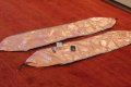
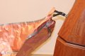
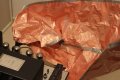
מזמן אני חושב לבנות כבל "ריבון",כידוע האלקטרונים בכל מוליך זורמים על פני שטח המוליך,מין אפקט הנקרא "סקין אפקט",כלומר בכבל רמקול המורכב מגיד סוליד קור 2 מ,מ אין כמעט שטח להוביל את הזרם מהמגבר לרמקול ,דבר הפוגע במהירות וברזולוציה ,במיוחד בגבוהים ,
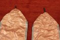
והנה נפל לידי ריבון נחושת משובחת ברוחב של כ40 סנטימטר ,כלומר לאלקטרונים יש שטח לזרום של 80 סנטימטר משני צידי הריבון(פס מתכת שטוח ,
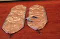
כך נגזר לו הפס לחתיכות של שני מטר ברוחב 40 סנטימטר , הדבקת בידוד שקוף משני צידי המתכת ,התקנת בננות בעדינות(החומר יותר דק מנייר אלומיניום למטבח) ,וחיזוק כל העסק שיעמוד בפגעי הזמן,
והרי התוצאה - בהמשך איך נשמע.


מזמן אני חושב לבנות כבל "ריבון",כידוע האלקטרונים בכל מוליך זורמים על פני שטח המוליך,מין אפקט הנקרא "סקין אפקט",כלומר בכבל רמקול המורכב מגיד סוליד קור 2 מ,מ אין כמעט שטח להוביל את הזרם מהמגבר לרמקול ,דבר הפוגע במהירות וברזולוציה ,במיוחד בגבוהים ,
והנה נפל לידי ריבון נחושת משובחת ברוחב של כ40 סנטימטר ,כלומר לאלקטרונים יש שטח לזרום של 80 סנטימטר משני צידי הריבון(פס מתכת שטוח ,
כך נגזר לו הפס לחתיכות של שני מטר ברוחב 40 סנטימטר , הדבקת בידוד שקוף משני צידי המתכת ,התקנת בננות בעדינות(החומר יותר דק מנייר אלומיניום למטבח) ,וחיזוק כל העסק שיעמוד בפגעי הזמן,
והרי התוצאה - בהמשך איך נשמע.
תמונות מצורפות
שניצל
חבר משקיען
- הודעות
- 8,043
- מעורבות
- 1,485
- נקודות
- 113
איך נשמע הסדין החשמלי.
שמעתי לבד , לא האמנתי למשמע אוזני ,אז הזדרזתי לקרוא לאיתן לוין,בכדי שתיהיה עוד אוזן לאשר לי את אשר אני שומע,
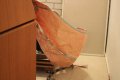
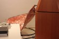
כל הכבלים שלי ממקודם נשמעים סגורים וטיפה סתומים יחסית"לסדין" ,אין סוף לגבוהים שלו ,אבל העניין הוא שהוא לא דופק את המיד או הנמוכים,דווקא הם נשמעים נהדר ,ריאליסטים ושקופים ביותר ,יחסית לכבל הזה הכל נשמע טיפה עמום בכבלים האחרים ,
גם הבמה קיבלה עומק ורוחב משופרים,באמת כבל ניפלא ,רק מה הבעיה?לך תשאיר אותו מחובר ברוחב הזה ?עכשיו מפתחים רעיונות איך לגלגל או לקפל אותו לרוחב הגיוני ,הרי זה קצת מוגזם לחבר סדין נחושת ברוחב של 80 סנטימטר מאחרי הרמקול
שמעתי לבד , לא האמנתי למשמע אוזני ,אז הזדרזתי לקרוא לאיתן לוין,בכדי שתיהיה עוד אוזן לאשר לי את אשר אני שומע,
כל הכבלים שלי ממקודם נשמעים סגורים וטיפה סתומים יחסית"לסדין" ,אין סוף לגבוהים שלו ,אבל העניין הוא שהוא לא דופק את המיד או הנמוכים,דווקא הם נשמעים נהדר ,ריאליסטים ושקופים ביותר ,יחסית לכבל הזה הכל נשמע טיפה עמום בכבלים האחרים ,
גם הבמה קיבלה עומק ורוחב משופרים,באמת כבל ניפלא ,רק מה הבעיה?לך תשאיר אותו מחובר ברוחב הזה ?עכשיו מפתחים רעיונות איך לגלגל או לקפל אותו לרוחב הגיוני ,הרי זה קצת מוגזם לחבר סדין נחושת ברוחב של 80 סנטימטר מאחרי הרמקול

daz
חבר משקיען
- הודעות
- 931
- מעורבות
- 121
- נקודות
- 43
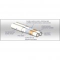
אסור לעשות את זה ברגע שאתה מגלגל ומשחיל לצינור זה כבר מאבד את ההשפעה של מוליך שטוחלא כל כך הבנתי למה זה טוב יותר ........... הרי בכל מקרה הכל מתנקז לבננות ששטח החתך שלהם קטן בהרבה אלא אם כן הם בנויות ממוליך על ..........
בכל מקרה אתה יכול לגלגל אותם כמו נייר ולהשחיל בצינור.
ברגע שאתה עוטף בצינור חלול - לאויר יש התנגדות אין סופית ..וזה נותן את היתרון של ההולכה על המשטח החצוני
שניצל
חבר משקיען
- הודעות
- 8,043
- מעורבות
- 1,485
- נקודות
- 113
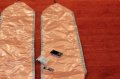
בכלל לא! שם הם משתמשים במיילר נחושת ,מעליו רשת ,שהיא המוליכה של הסיגנל ,הרשת בנויה מחוטים חוטים,איפה אתה רואה אצלי רשת ,יש את זה גם באנליסיס ,בנינו פעם אני וצחי משהו דומה עם ציפוי זהב ,כבל טוב מאוד ,אבל לא קרוב לסדין ,משהו אתה לא מבין ,אבל השטח של הסדין יותר מפי עשר מאשר הדוגמא שהבאת

תמונות מצורפות
שניצל
חבר משקיען
- הודעות
- 8,043
- מעורבות
- 1,485
- נקודות
- 113
אם מגלגלים בלי לבודד ,מתכת תגע במתכת וכך אובד לו הייתרון של שטח פנים גדול ,לגבי הבננות ,חשוב גם מהקורה בין 2 בננות בכבלֿלא כל כך הבנתי למה זה טוב יותר ........... הרי בכל מקרה הכל מתנקז לבננות ששטח החתך שלהם קטן בהרבה אלא אם כן הם בנויות ממוליך על ..........
בכל מקרה אתה יכול לגלגל אותם כמו נייר ולהשחיל בצינור.
daz
חבר משקיען
- הודעות
- 931
- מעורבות
- 121
- נקודות
- 43
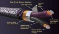
בכלל לא! שם הם משתמשים במיילר נחושת ,מעליו רשת ,שהיא המוליכה של הסיגנל ,הרשת בנויה מחוטים חוטים,איפה אתה רואה אצלי רשת ,יש את זה גם באנליסיס ,בנינו פעם אני וצחי משהו דומה עם ציפוי זהב ,כבל טוב מאוד ,אבל לא קרוב לסדין ,משהו אתה לא מבין ,אבל השטח של הסדין יותר מפי עשר מאשר הדוגמא שהבאת
צפה בקובץ המצורף 14376
בגלל זה אני אומר תשתמש בצינור יותר רחב בקוטר. אני לא יודע כמה זה ישים
בכול מקרה בהצלחה ב DIY
")
daz
חבר משקיען
- הודעות
- 931
- מעורבות
- 121
- נקודות
- 43
חח.. השם האמיתי שלי דוד אזולאי DAZ זה רק כינו כמו טאז השד הטזמאניvas is "daz
בהצלחה בפרויקט אחי אני תמיד מעריך יצירתיות ב DIY
NStudio-Hiend
חבר משקיען
- הודעות
- 851
- מעורבות
- 43
- נקודות
- 28
בתדרי השמע אין תופעה כזאת שנקראת skip effect וזה קורה בתדרים מאוד גבוהים כמו תדרי רדיו ......
הכבל שבנית כנראה בגלל הגאומטריה שלו נתן לך אפקט אחר וכנראה גם טוב יותר מהכבלים היקרים שברשותך .
3. THE "SKIN EFFECT"
The distinction between the skin effect and self inductance may be a subtle to some, but not to those that truly understand the implications of the phenomenon. Contrary to the superficial propaganda parroted by the majority of the high end audio cable industry, the skin effect by itself is only relevant to very high radio frequencies (well beyond audio) and the all-too-often heard statement that "the high audio frequencies ride on the edge of the wire" is completely wrong. Only very high radio frequencies (Mhz) ride on the edge of a conductor. Therefore the "skin effect" has very different implications for the complex audio signal which consists of "bundles" of multi-frequency information spanning a very large range than it does for simple RF (radio frequency) carrier signals.
It is really the ORIGIN of the skin effect, self-inductance, not the skin effect itself, that can produce the group delay that is relevant to audio. The significance of self inductance to the audio signal is a gradient of differential resistance which has the potential to attenuate the power of the individual components of these multi-frequency "bundles" and thus introduce slight time delay's relative to each other. Otherwise, the end result of self-inductance, the "skin effect", is simply a rising DC resistance to rising frequency such that at highest frequencies (way up into the Megacycle range) DC resistance becomes so high (due to such a minute portion of conductive area available) that it becomes very significant and should be factored into impedance calculations to find the true impedance (resistance to alternating current). Normally, DC resistance of the conductor itself is dropped out of the equation for impedance for the "low to mid RF" range and is not a factor except for at AUDIO frequencies and very high Radio Frequencies.
The reason higher frequencies are continually pushed out from the center of the conductor to their ride depth (the "skin" of the wire) is due to a force, the changing magnetic field, which is produced by the rapidly fluctuating AC current. This force is a result of self-inductance which is a phenomenon resulting in the opposition to a change in direction of a signal (AC) due to locally circulating "eddy currents." Therefore, the deeper the frequency penetrates, the more it is damped, until it reaches an energetic equilibrium, which becomes its depth of penetration or "ride depth". This is analogous to the way quicker temperature changes penetrate a shorter distance into thermal-conductors than slower ones per unit of time.
This "skin depth" is often decided on from a common formula; (depth of penetration=1/sq root (frequency*pi*magnetic permeability*conductivity) to calculate the depth to which, for example, a 20K frequency will penetrate. From this formula one might mistakenly conclude that we only need to use a conductor whose radius is smaller than the depth of penetration of the highest frequency in audio (20 khz). Also, from this formula it is evident that Silver wires actually have an even shorter depth of penetration necessitating even smaller conductors than copper! This is because of the different conductive characteristics of Silver.
What is overlooked is how the depth of penetration formula was derived. In today's convenient formula based engineering world, there are many assumptions "built in" to all standard formulas, such as the 3dB, half power point in capacitance/resonance formulas. To calculate to what depth a given frequency penetrates is a function of to what degree the frequency is attenuated since it is a continuously increasing effect. The above formula actually yields the 1/e depth to which a frequency penetrates before it is damped to a 64% power loss which relates the shoulder of a sigmoid curve and thus normally a fair point to base further calculations on. We may calculate, if we want, the distance a 20Khz wave would penetrate before it is 99% damped which as you might expect, is greater. If however, we calculate the distance it can travel before it is only 1% damped, for instance, we find it is much shorter and well within the smallest conductor size used in virtually any audio cable! This formula is very conservative when applied to audio because it and others were originally derived for application in radio communication electronics where the skin effect is a vastly more serious problem due to the much higher frequencies (Mhertz and up to GHz) involved. Why should we allow any damping which is (in principle at least) a source of phase distortion when we can minimize it so easily by simply discarding with the ever present and almost universally untrue "bigger is better" "phalacy" (pun intended)?
In the light of all this, the sensible choice is simply to use conductors that are as small as possible to keep this gradient of differential resistance as short as possible which is why Silver Audio has always used multiple, very small, individually insulated conductors (the popular "Litz" concept) in place of one larger one. This is one of the two reasons we use two or more runs of the smallest feasible gauge pure Silver conductors in all our designs.
נערך לאחרונה ב: